Tuesday, 2 October 2012
Semester 2 Week 9
TITLE :
Making the generator.
OBJECTIVE:
To build the 12V custom generator.
CONTENT:
this are the materials needed for making the generator.
1) magnet
2)copper wire
3)glue
4)pro-spec
5)plywood
6)cable tie
Basically, in order to make any type of the generator, the concept is the same.
here is the useful link that help me to make my generator.
http://www.miniscience.com/kits/woodengenerator/index.html
this link, teaches how to make wooden generator and some justification on why the problem occurs when testing the generator.
i followed the steps from the above links, but had adjusted a bit because i'm not making wooden generator. The design of my generator and the materials i'm using doesn't imitate from the links due to my design the and environment place which where i placed does not suitable for wood generator (hydro generator).
1) i make 6 coils where each coil contains 200 turns
2) i attached 6 neo-dynium magnet to a circle pro-spec using glue.
3) i attached those 6 coils onto the plywood using cable tie.
CONCLUSION;
Making the generator is done but still need to test the generator because i need o know how either its working or not and how many the voltage being produce and minimum rp. that i need in order to produce 12V.
Semester 2 Week 8
TITLE:
The idea for making a custom 12V generator
OBJECTIVE:
To find a suitable generator for the project.
To understand how to built a generator.
CONTENT:
I need to find a generator that produced 12V which suits the project well. after doing some research on the generator (theory parts) and with the helps from this video, i was thinking to build the generator with custom made generator which can produce 12V output voltage. the materials needed to build the custom generator are; 6 pieces of neo-dymium magnet, copper wire, pro-spec, plywood and cable tie.
CONCLUSION:
need to purchase the materials and need to start doing the custom generator ASAP.
Semester 2 Week 6 and 7
TITLE :
Design and build the main structure of the project.
OBJECTIVE :
To build the projects.
To get the best design for hydro generator.
To get the material for the actual design
CONTENT:
I went to the half cut shop, hardware, motorcycle shop,grocery, fishing shop, bicycle shop buy the things that needed to build the main and overall structure of my projects. Below are the lists of the thing I bought from the hardware, grocery shop ets.
1. Ex5 cover clutch
2. Spoons
3. Ball Bearings
4. Angle Bar
5. Jointer of the angle bar
6. Bolts and nuts
7. Hose pipe
8. Pipe and accessories
9. Spray
10. Aquarium (plastic)
11. Chain
12. Gear
13. Flywheel gear
All the listed items are not all of them are easy to find, it take time to go survey and finding all the items .After all the items i have. then i proceed to do the next step.
 |
| Angle bar |
With the angle bar and the accessories that i bought, now im going to cut them join them with the jointer, bolt and nuts. It is not easy to cut them with the saw, it really sweats me a lots. i have to measure all them to make it perfectly accurate to the size or else it will not give me the right size. Besides, it will give some difficulties to joint each other.
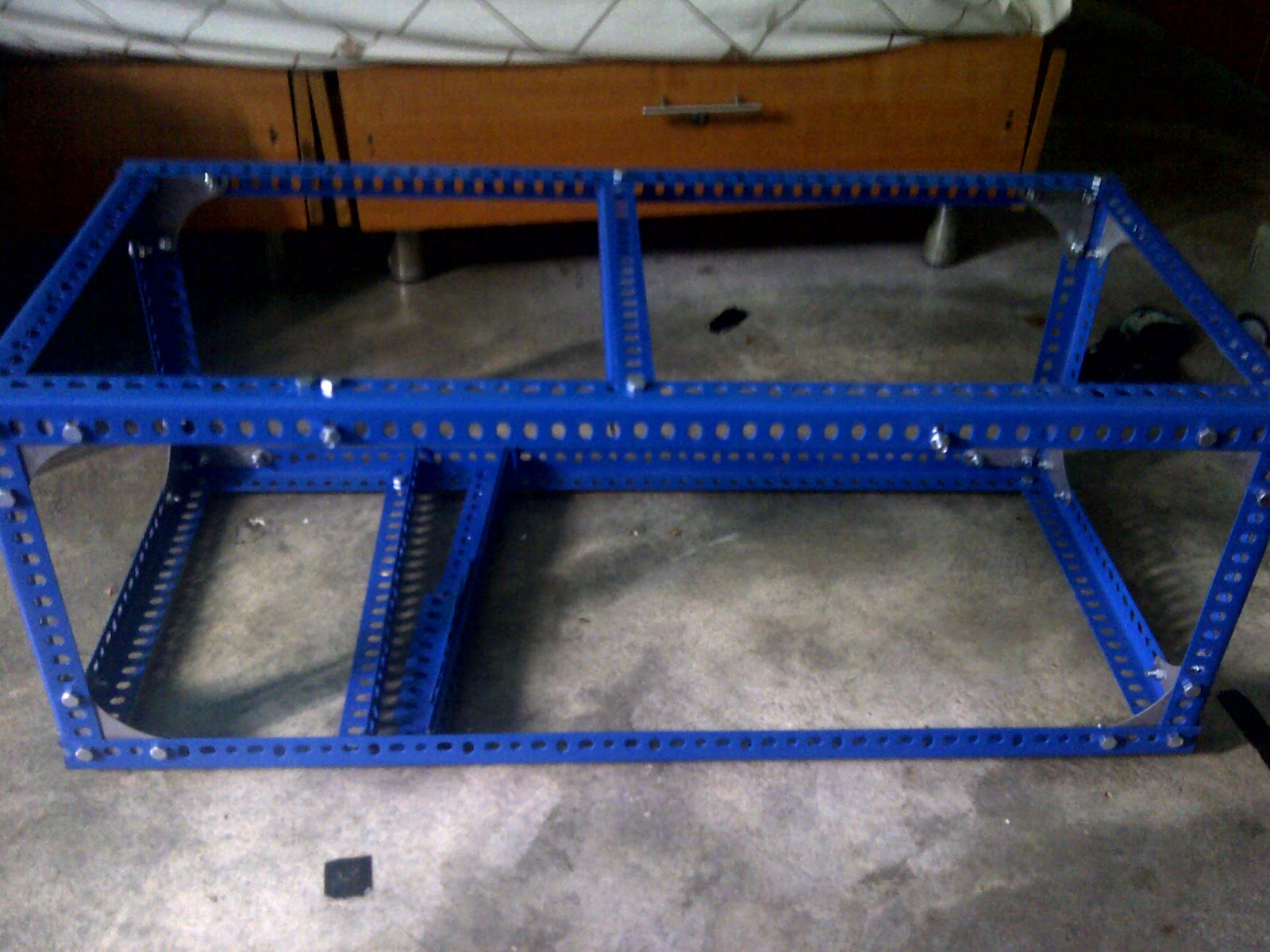 |
| The structure of the design |
CONCLUSION:
After all the hardship to find the item and build it, now i can see almost the actual of the project. from now i can proceed to next step which are combing all the items together. But some of the items need to do through welding shop.
Semester 2 Week 4 and 5
TITLE:
Finalize the Inverter Circuits
OBJECTIVE:
To assemble the components.
Solder th components leg
To test the circuits
To placed the inverter circuit and transformer in 1 place.
DISCUSSION/ANALYSIS:
Before assembling the component. I have to check the polarity of the each components such as positive and negative of the diodes, the capacitor, the e-b-c for transistor to avoid misplaced which can damage some of the components. Place the component correctly and do double check before soldering
Soldering one by one and solder the components leg carefully to avoid damage of the circuit and the components itself. After done soldering all the components leg are not being cut for future arrangement if the mistake or misplace occurs.
Every electronics and electric can harm people. so it must have the cover, a safe one. After successfully construct the inverter i decide to place them together and sealed as well for unreachable from people and to make my projects have a safety precaution.
I decide to make the cover from acrylic (pro-spec) because it easy to cut them and place the plug, fan and whatsoever in one place.


CONCLUSION:
The inverter circuit input and output have been tested and checked. There is no problem for the circuit. the cover for the circuit also have been build and as well as the plug and fan have been installed altogether in one box. Proceed to next stage.
Wednesday, 12 September 2012
Semester 2 Week 3
TITLE:
Start buying the component and transformer.
Start buying the component and transformer.
OBJECTIVE:
To get the components for the inverter circuits.To assemble components.
DISCUSSION/ANALYSIS:
This week i went to Jalan Pasar to get this components:
1. 14 resistor which each have their own value
2. 4 diodes
3. 2 diode zener
4. 8 transistor (mosfet)
5. Ic LM555N (timer)
6. 2 E-capacitor
7. 2 Ceramic capacitor
8. Relay of 12V (5 pin)
9. Transformer 5A 12V-240V
10. Fuse
11. PCB board
Below are the components that had been bought at Jalan Pasar to make an inverter circuit.
Before assembling the components, the PCB board need to sketch first. Sketch the connection of the components using the special marker to do the sketch. Here is the picture of the PCB which had been done.
After finish the sketching, i use the acid water to remove unwanted copper in the PCB. In order to get the sketching printed in the PCB i have to dip in the acid water and spin the acid for about 45 minutes to get the copper remove and the printed copper remain.Below are the results of the the PCB that have been hatching.

Although there are some connection are loss due the hatching i can fix it with multimeter to check the connection continuity, solder and sand paper. to repair the losses of the connection due the hatching, First need to test the continuity with refering to the circuit diagram. Find the the losses along the connection then solder it to joint each other. Use sand paper make it thinner and softer. Refering to the picture above, the silver colour is the joint made from solder.
This week i went to Jalan Pasar to get this components:
1. 14 resistor which each have their own value
2. 4 diodes
3. 2 diode zener
4. 8 transistor (mosfet)
5. Ic LM555N (timer)
6. 2 E-capacitor
7. 2 Ceramic capacitor
8. Relay of 12V (5 pin)
9. Transformer 5A 12V-240V
10. Fuse
11. PCB board
Above are the components which are needed to build an inverter circuit its not cheap and very sensitive and its expensive. For the transformer there is ready made sell at Jalan Pasar.
Below are the components that had been bought at Jalan Pasar to make an inverter circuit.
 |
| The Inverter components. |
Before assembling the components, the PCB board need to sketch first. Sketch the connection of the components using the special marker to do the sketch. Here is the picture of the PCB which had been done.
 |
| Sketching the PCB |
After finish the sketching, i use the acid water to remove unwanted copper in the PCB. In order to get the sketching printed in the PCB i have to dip in the acid water and spin the acid for about 45 minutes to get the copper remove and the printed copper remain.Below are the results of the the PCB that have been hatching.
Although there are some connection are loss due the hatching i can fix it with multimeter to check the connection continuity, solder and sand paper. to repair the losses of the connection due the hatching, First need to test the continuity with refering to the circuit diagram. Find the the losses along the connection then solder it to joint each other. Use sand paper make it thinner and softer. Refering to the picture above, the silver colour is the joint made from solder.
CONCLUSION:
The component have been bought and hatching the PCB also had been successfully been made. The connection of the PCB has been tested and the hole on the PCB for the components leg have been done. Now i can proceed to next stage.Semester 2 Week 2
TITLE:
The Inverter Simulation
The Inverter Simulation
OBJECTIVE:
To test the inverter circuits base on simulation.To check the connection of the components.
To investigate the results.
DISCUSSION/ANALYSIS:
I have done some research before on building the inverter circuit. so for my projects, i will need inverter to change the DC sources to AC sources. My projects will have 2 output sources which is 12V DC and 230V AC. But in order to get the AC signal. The inverter circuit is needed while to have the 230V output.
I have done some research before on building the inverter circuit. so for my projects, i will need inverter to change the DC sources to AC sources. My projects will have 2 output sources which is 12V DC and 230V AC. But in order to get the AC signal. The inverter circuit is needed while to have the 230V output.
Below are the simulation results and the connection of the components in an inverter circuits
 |
| The connection and the results for the simulation. |
CONCLUSION:
The circuit had been tested, the connection is correct and the results for the simulation have been obtained. The simulation on inverter circuits is successful and now i can proceed to next stage which is do the actual inverter circuits.
Semester 2 Week 1
TITLE:
Start to types the thesis for chapter 1, 2 and 3. Also do some findings and survey for the hardware.
OBJECTIVE:
To finished the thesis chapter by chapter.
To identify where to find all the things needed for hardware installation.
DISCUSSION/ANALYSIS:
CONCLUSION:
The conclusion that can be made for this week is stay in front of the laptop and start to do a paper work and getting as much information from the hardware shop and electronic shop at Jalan Pasar. Succesfully submit the chapter 1 and chapter 2 to Sir Suhairi as a projects advisor. For the chapter 3, i cant submit it yet because it is not finished and it will stay as a draft for a while.
Subscribe to:
Posts (Atom)